


Tiny Game Jam
In Spring 2024, as the studios at Brightworks were wrapping up, I thought it might be cool to make miniature versions of some of the things our students had made in the various studios. Gever’s studio made a video game with a full-size arcade cabinet for it to go into, and inspired by a suggestion from Gever, that's what I chose to miniaturize.
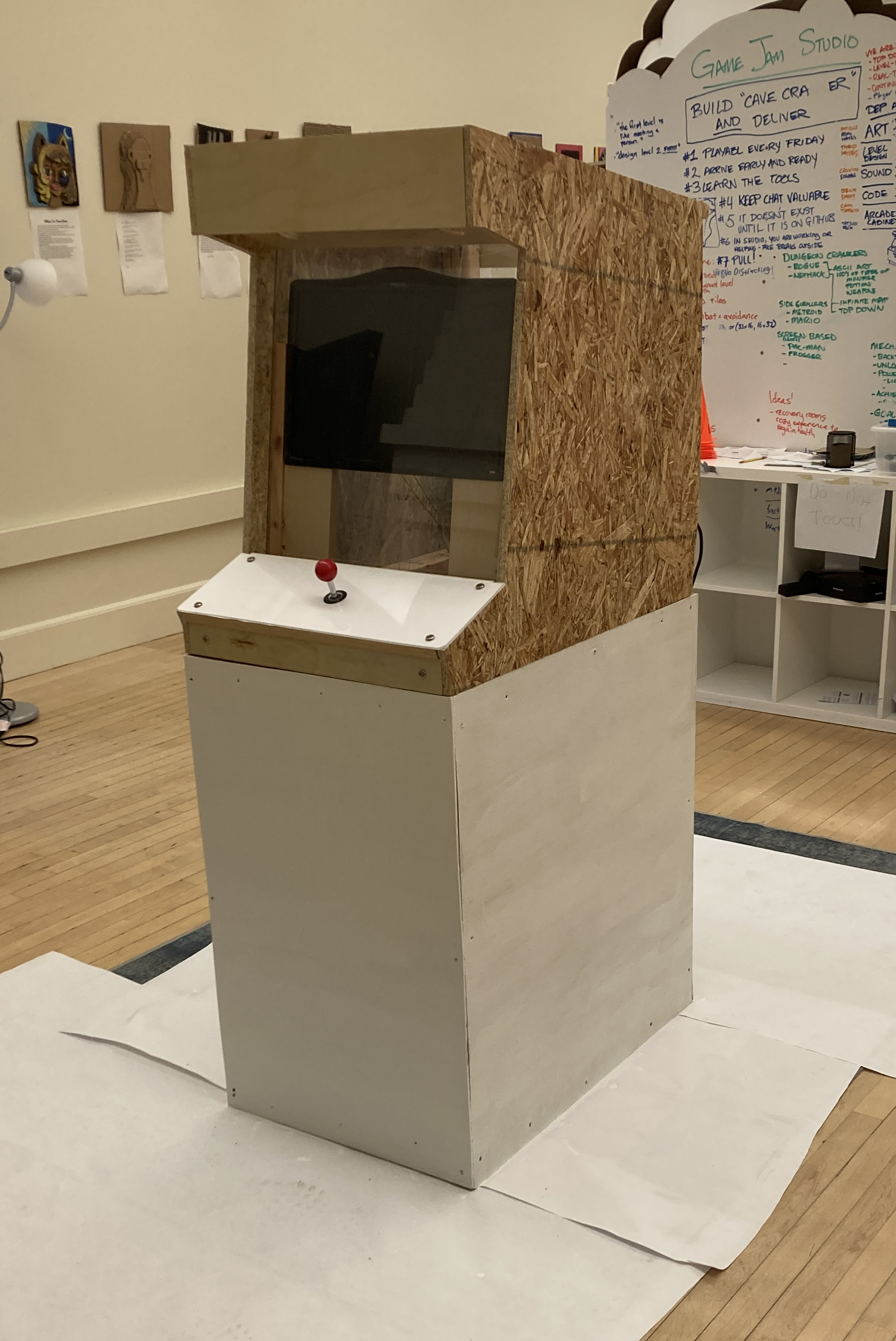
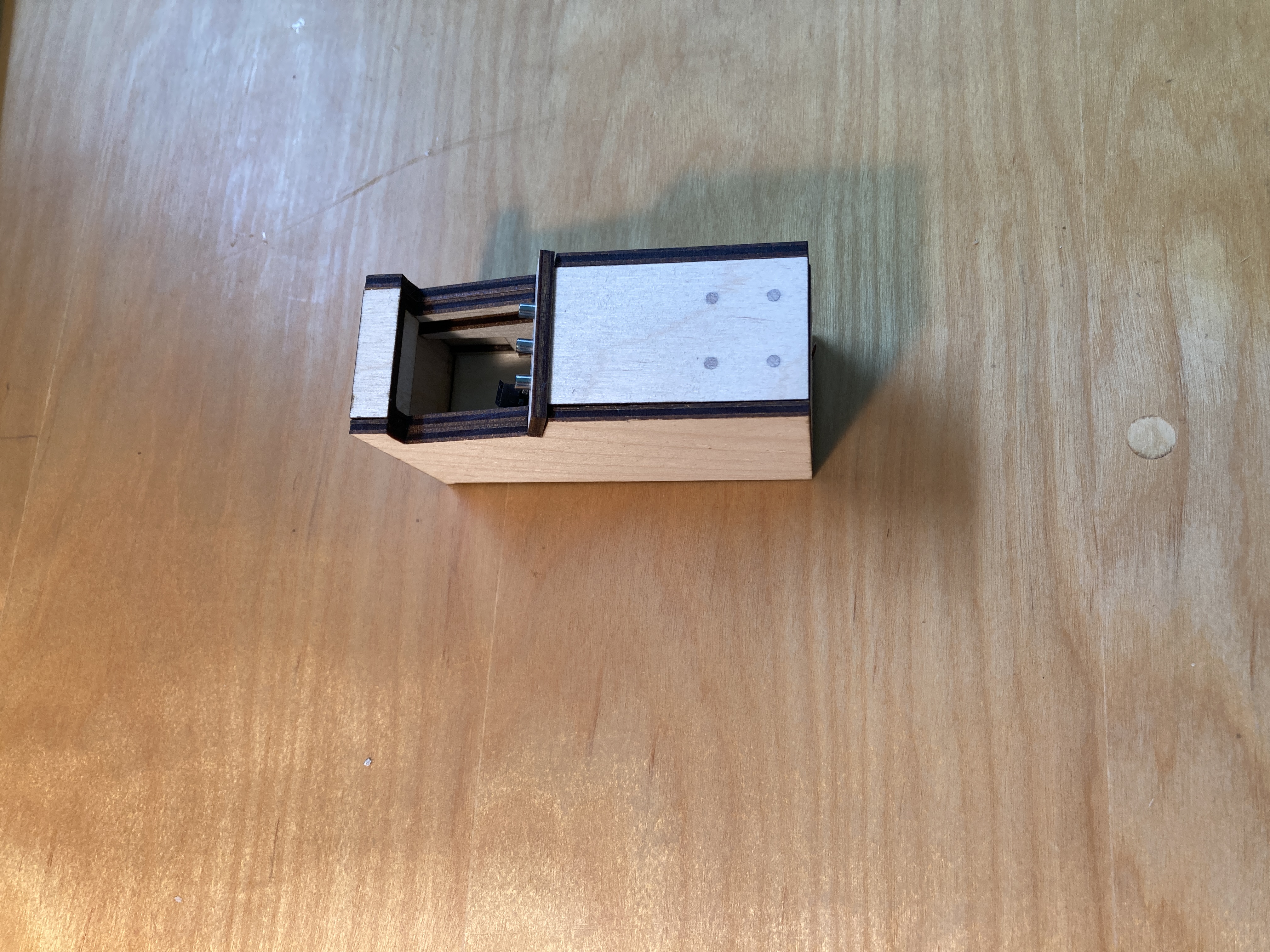
An Arcade Cabinet, But Tiny
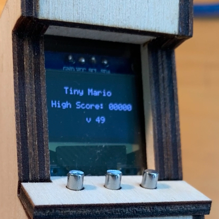
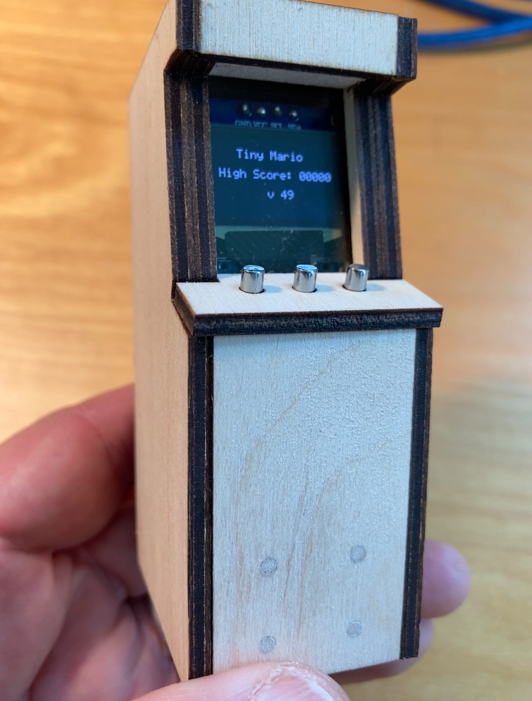
This is a faithful miniature version of that cabinet, designed in Rhino, and scaled to match the dimensions of a 128x64 OLED display. It has a functioning version of a Mario game, running on an ATTiny85 (an 8-pin microprocessor with 512 bytes of RAM and 8K bytes of ROM). It’s not only a fun hand held game, but it’s programmable, so anyone can add other games they may write for it. The Mario game on the current version is based on ATtiny85 Mario by shepherdingelectrons. That one was written to run on two OLEDs, and lacked features like a splash screen/title screen, and record of high scores; I added those features as I heavily modified the original ATTiny85 Mario code.
Features and Limitations
The game runs on an 8-pin microprocessor that’s in the Arduino family. But even with only eight pins (two of which must be used for power and ground), the hardware can handle up to two banks of three buttons each (and can detect simultaneous button pushes), AND drive a 128x64 OLED display, AND output music simultaneously with sound effects to a small speaker. The ATTiny85 runs at 16MHz, so gameplay is fairly snappy, and screen refresh rates are good.
That said, there’s only 8K of ROM (8192 bytes, precisely), of which I use 8154 bytes. And there's only 512 bytes of RAM for running the game program, of which I use 399 bytes even before runtime. If I use 401 bytes, visual artefacts appear on the display, so I'm right up against the RAM limit. In fact, the occasional odd squeal from the speaker results from (I suspect) my trying to do too much given this severe RAM constraint.
Hardware
Each bank of three buttons is attached to a single pin and clever use of resistors in line with the buttons, and analog-to-digital conversion by the ATTiny85 of the voltages flowing through those resistors, allows each button or combination of buttons to be distinguished. (This was designed by someone far cleverer than I; I just implemented it here.) I have more extensive technical comments on this in the source code itself.
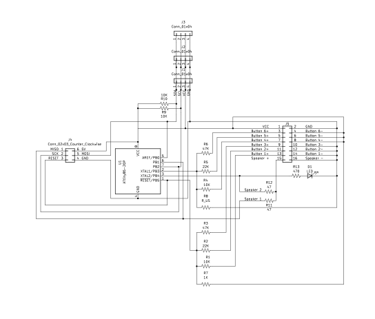
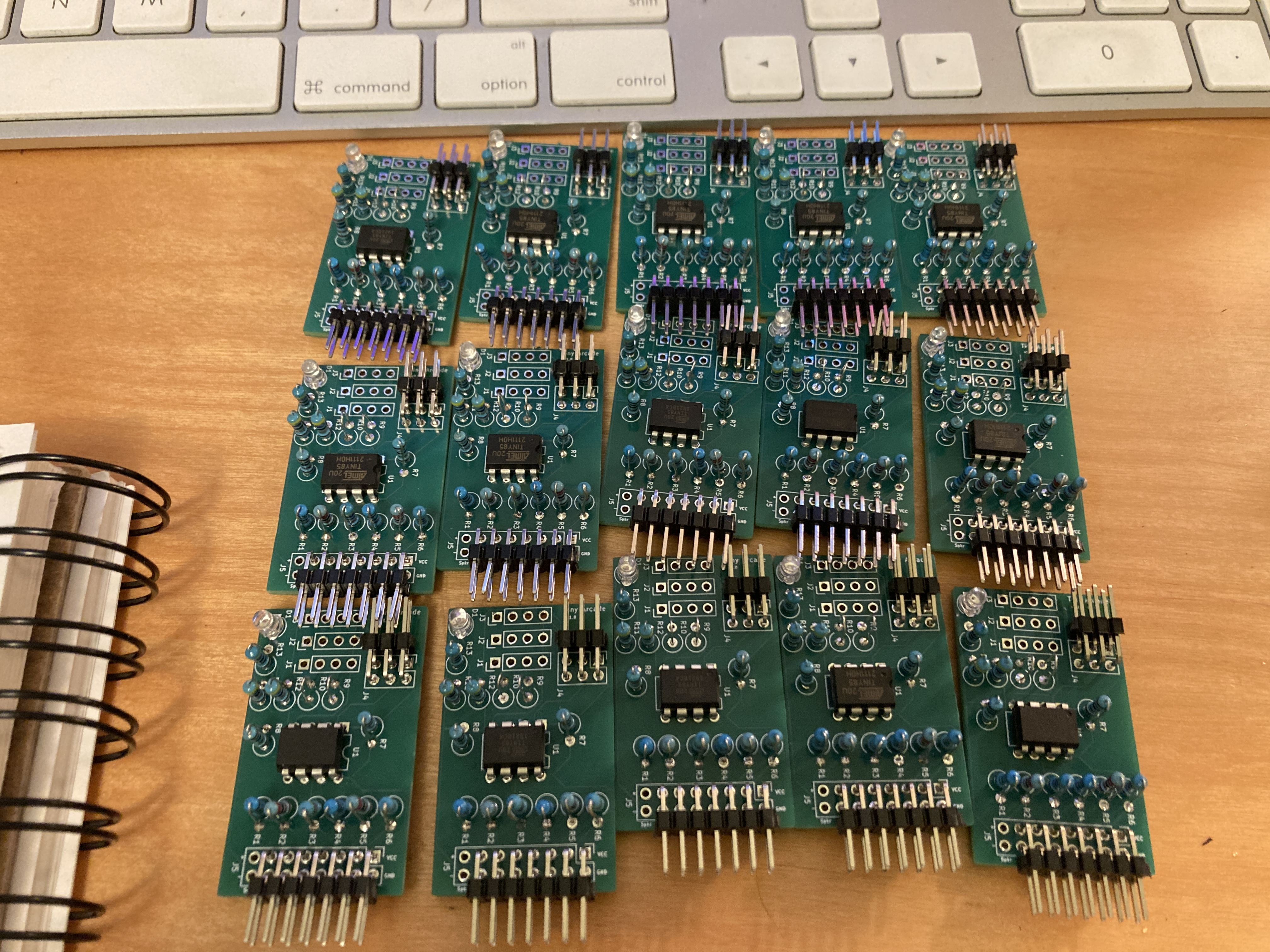
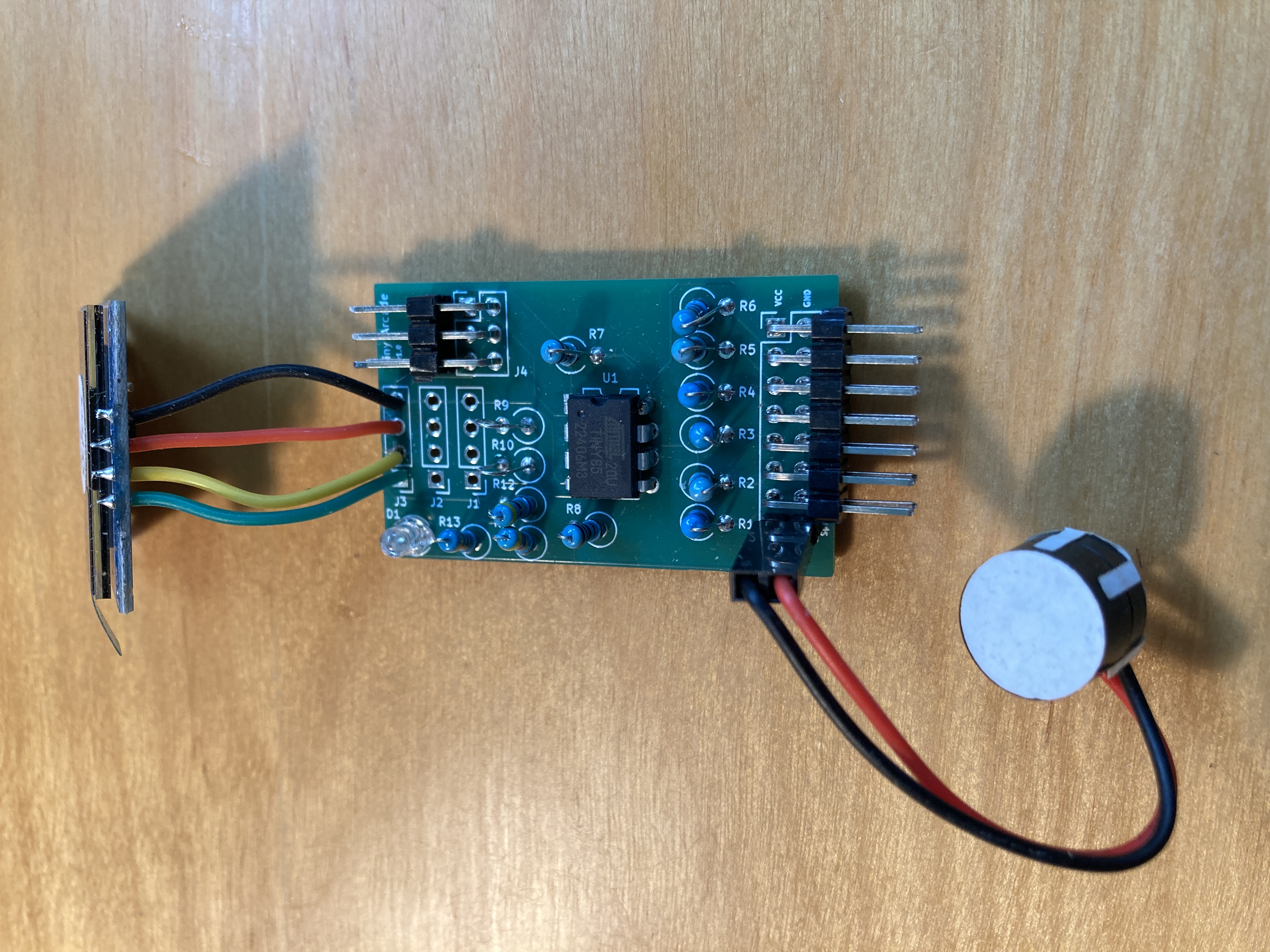
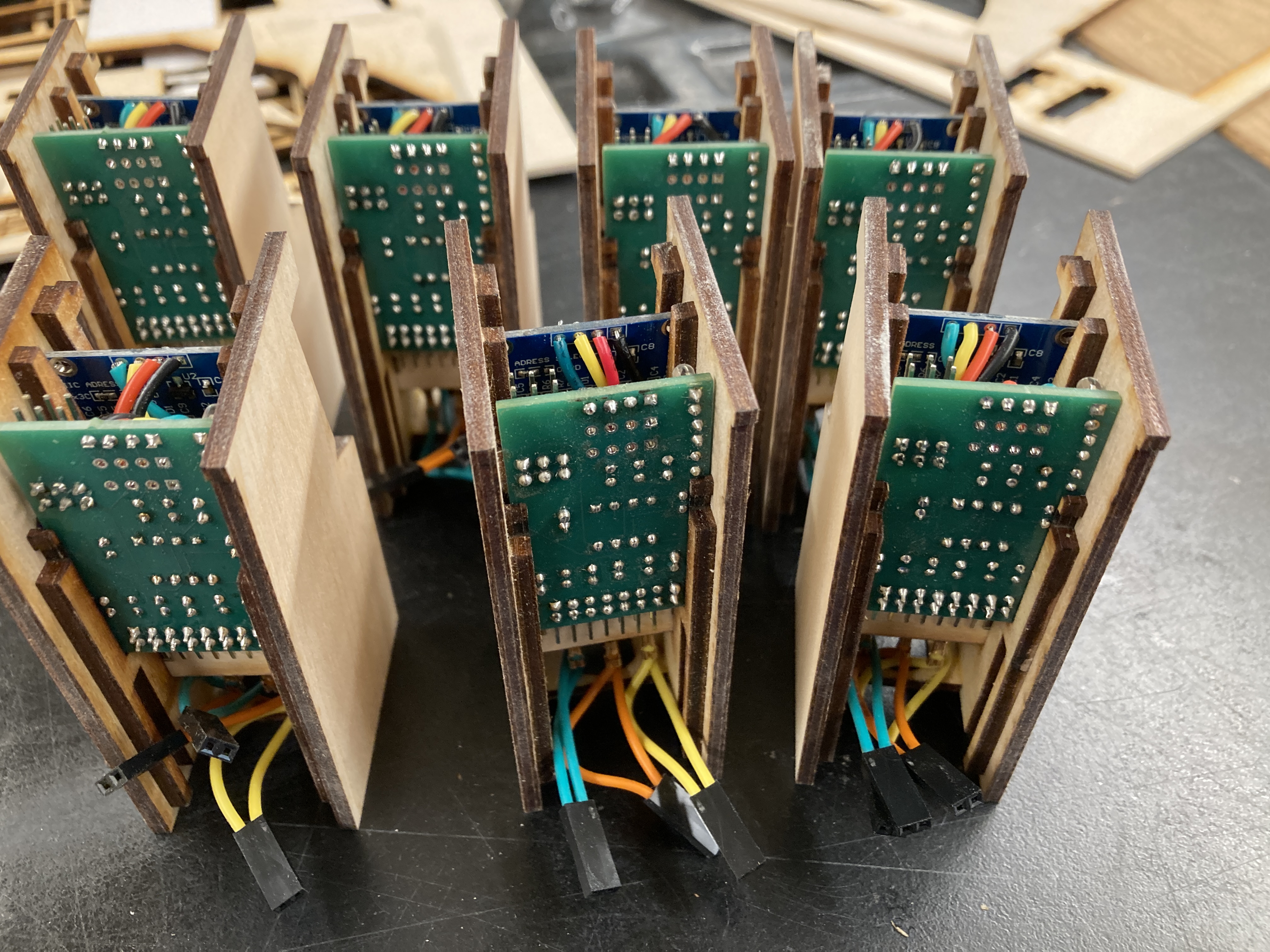
All the hardware revolves around a small printed circuit board I designed in Kicad and had manufactured by JLCPCB in China. The pcb includes the resistors for the buttons, the ATTiny85, a programmable LED, a few other resistors, and three headers: a 2x3 pin header for programming the ATTiny85 (more on that below), a 2 pin header for the speaker, and a 2x7 pin header for power from the USB socket on the back of the console, and for the three buttons that are used (with space for three others) to plug into.
The Cabinet
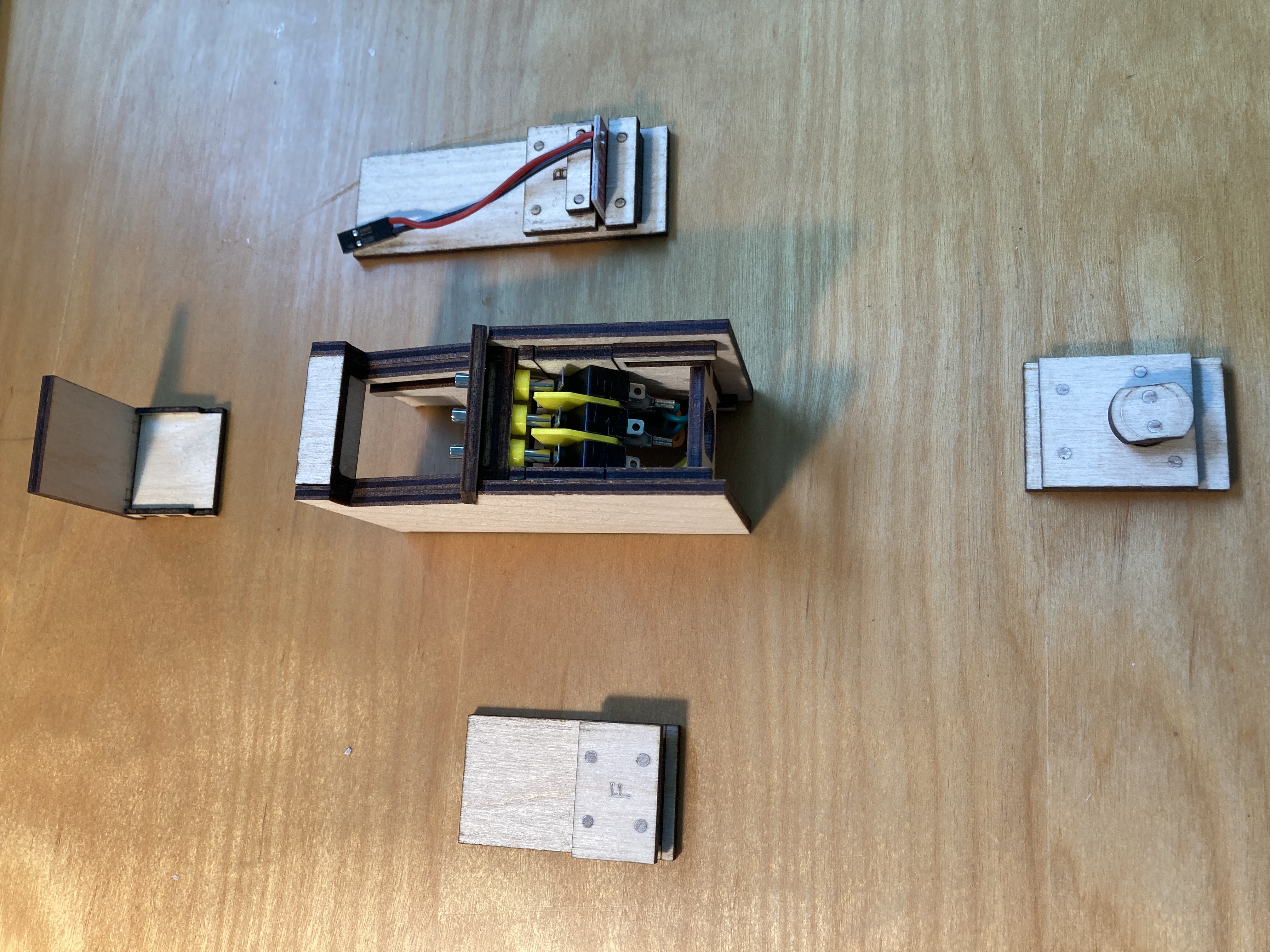
The tiny cabinet was designed to provide access to the internal components. To that end, it’s opened by inserting a coin in the slot on the bottom, and twisting the slot perpendicular to the display. The bottom piece should then be removable. With the bottom piece off, the front and back panels slide down and off. And with the back panel slid down, the top panel can come off. The OLED is connected to the pcb by soldered wires, and that whole assembly slides out the top of the cabinet after being disconnected at the bottom of the pcb from the buttons’ Dupont connectors.
Power is supplied through a USB-C connector on the back panel.
The Buttons
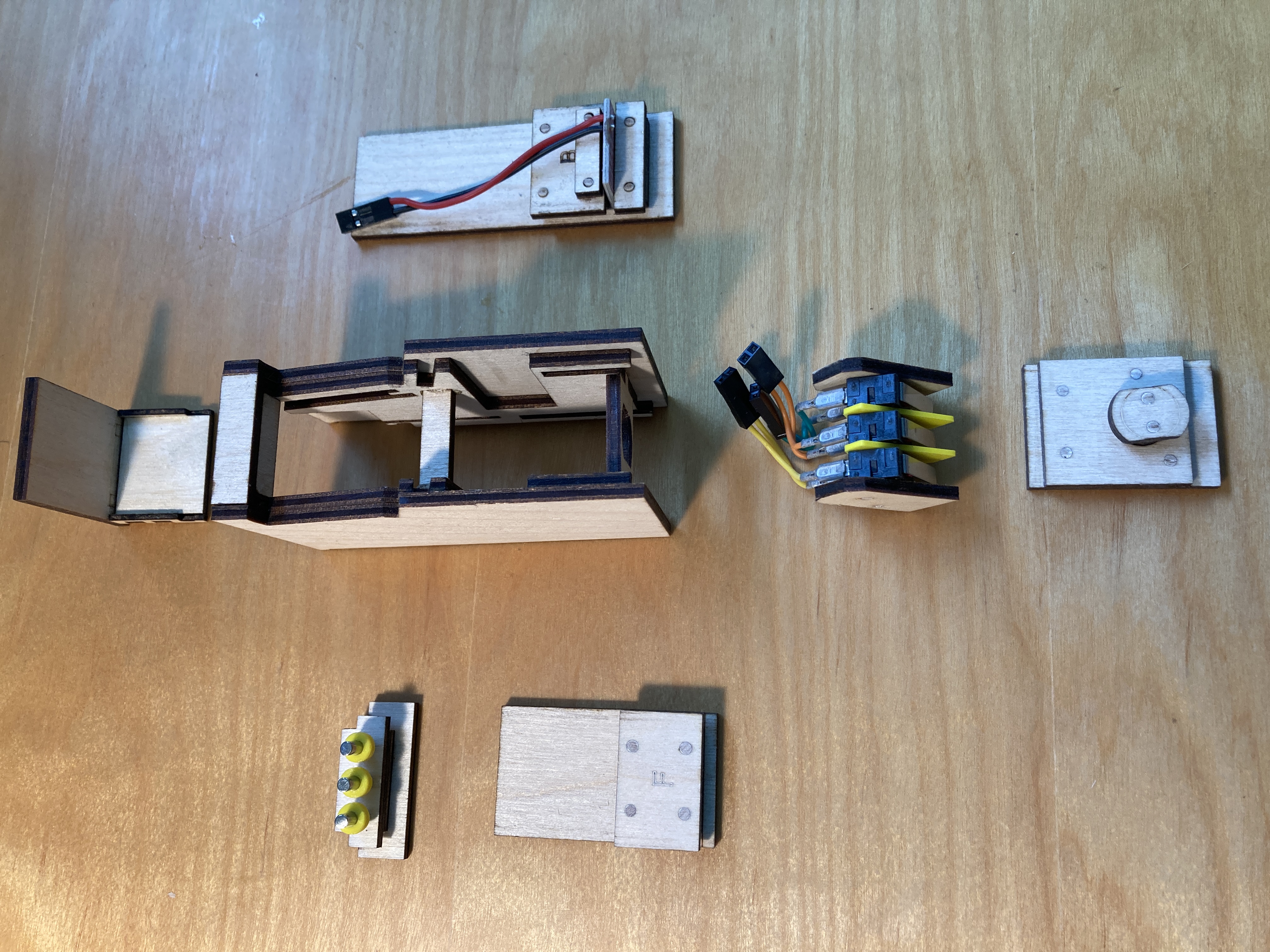
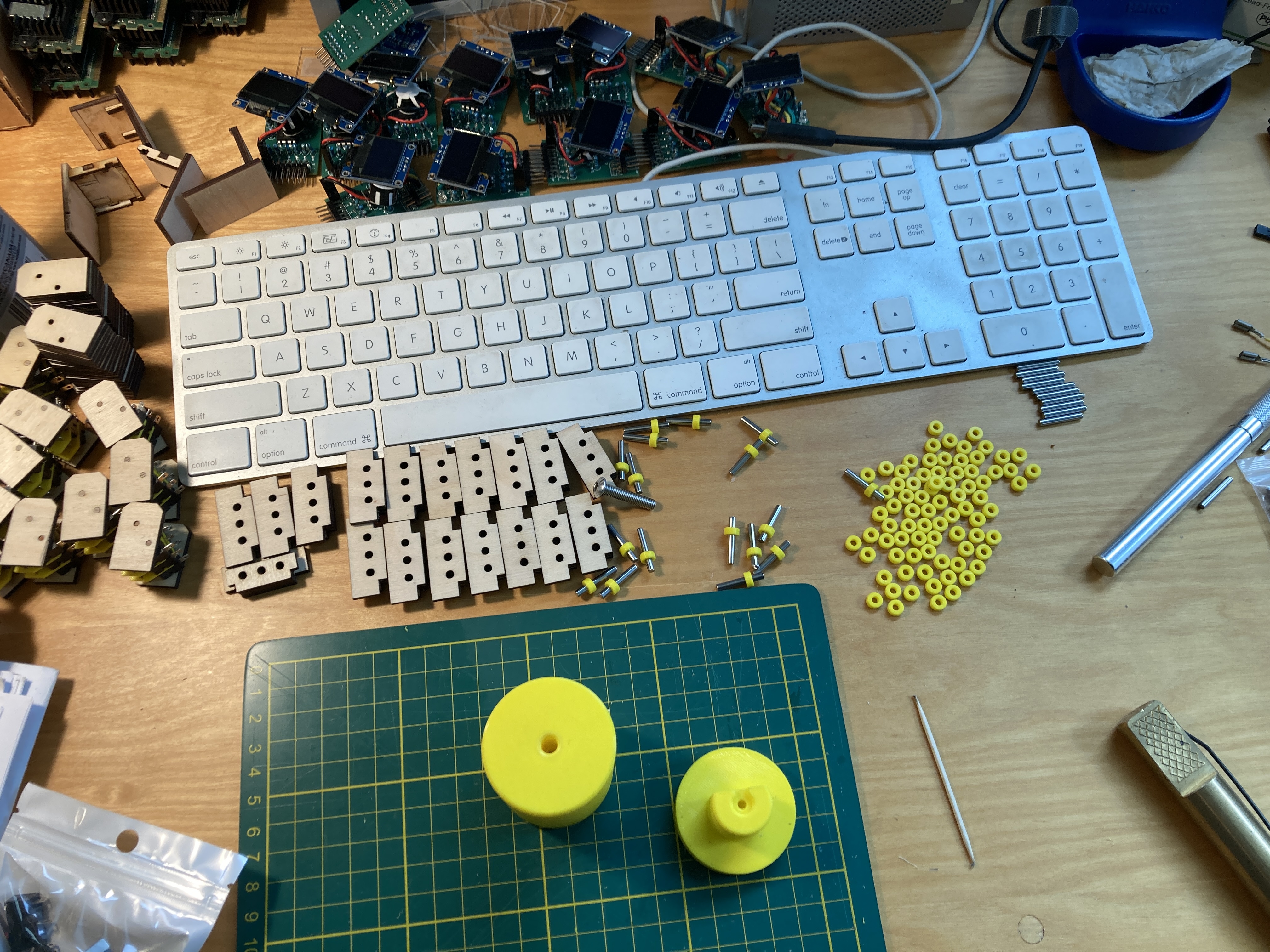
An early version of the Tiny Game Jam was unveiled at Brightworks’ Maker Marketplace in the Spring, and it was abundantly clear from people’s reactions when trying out the device, that the buttons made from laser cut plywood were entirely inadequate. Several iterations later, I settled on the current design that uses metal dowels and a few small 3d-printed parts.
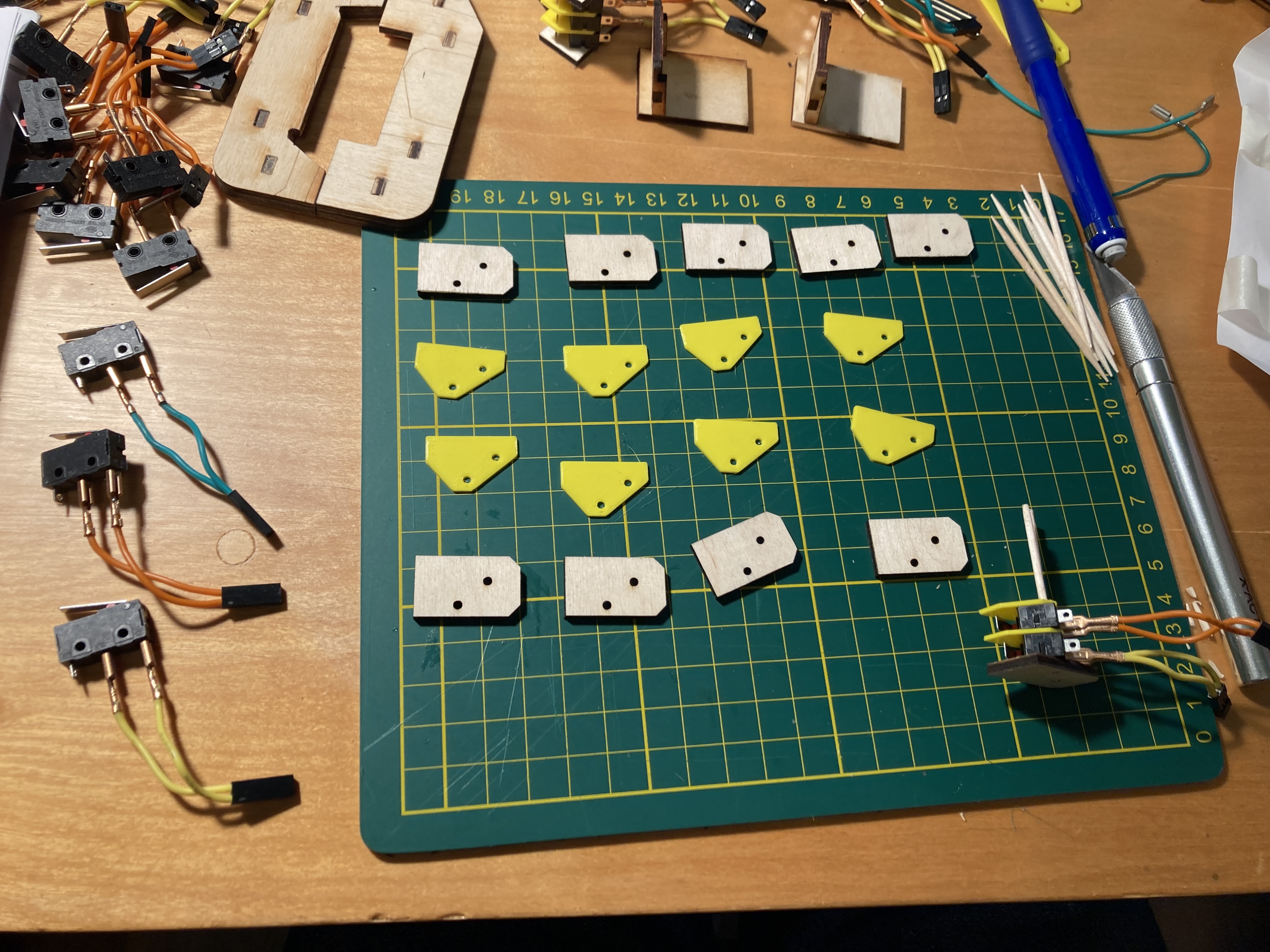
The buttons have two parts: a metal dowel that is the button one pushes, and the lever limit switch the dowel pushes against. The bank of dowels slides forward at an angle, and out of the cabinet, then the limit switch assembly can be slid back out of the front of the cabinet. The metal dowlels slide through a control panel made of three pieces of 3mm plywood (the whole cabinet is made of 3mm plywood, except two tiny pieces in the top that are made of 1.5mm plywood), and 3d-printed collars on the dowels (yellow in the photo) keep them from coming up out of the control panel. Dividers that are 1.1mm thick (3d-printed) keep each limit switch and its dowel from interfering with the others.
The Software
There are four software components: tiny_mario_49.ino (the main.c, but as used by the Arduino IDE), assets.h, and oled_lib.c and oled_lib.h.
The tiny_mario_49.ino file is the game program itself. As I said above, it’s based on the ATTiny Mario project, but I’ve heavily modified it and fairly generously commented much of it. To (1) add the title and game over screens, (2) keep all the music, and (3) save the high score to EEPROM so it’s available between gaming sessions, I had to make room in ROM (and RAM), so I eliminated partially completed work on pipes, goombas, and fireballs.
The assets.h file includes the hex representations of the numerals, letters, and punctuation (and of all the sprites) I use in the game. The music and sound effects are also here.
Finally, the oled_lib files are ones I got from the ATTiny Mario project mentioned above, and they have not been modified at all by me.
Programming the Console
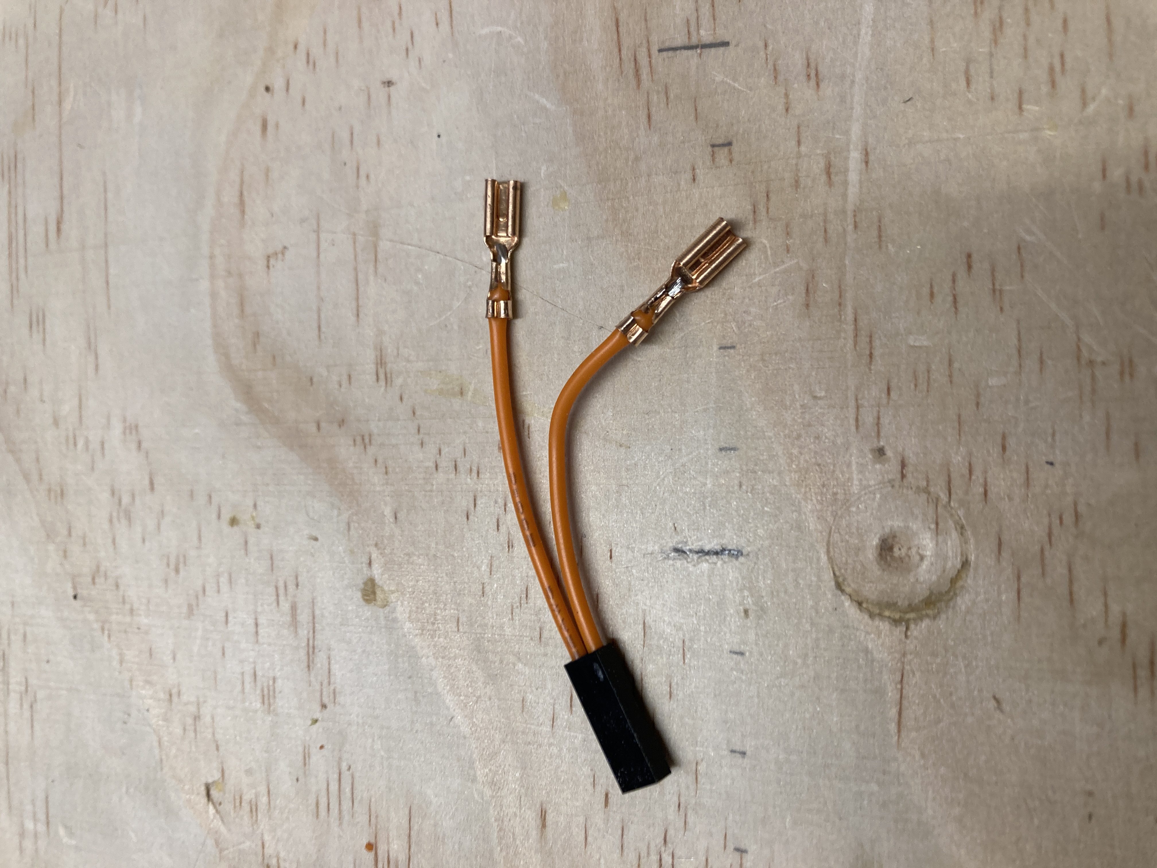
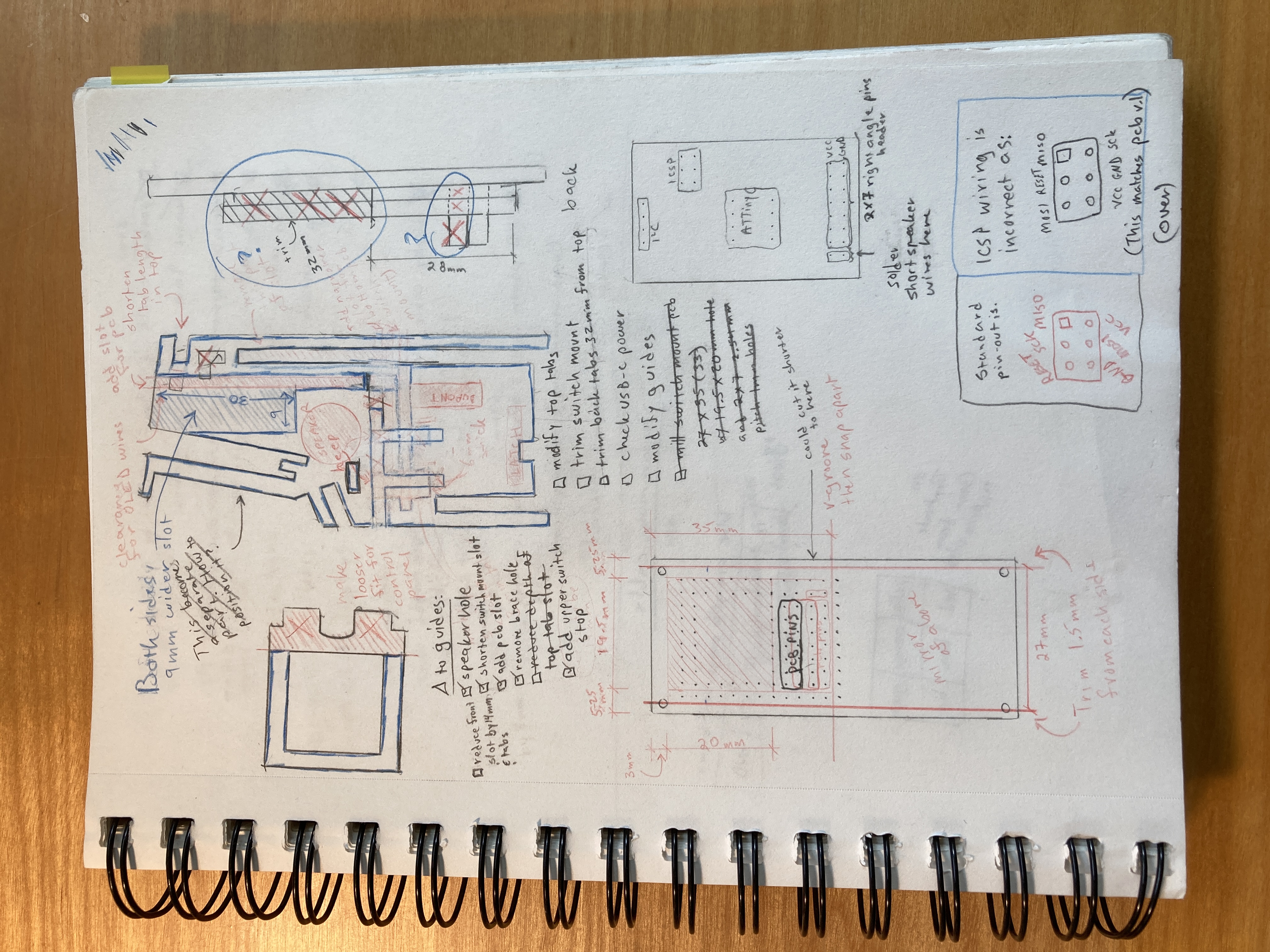
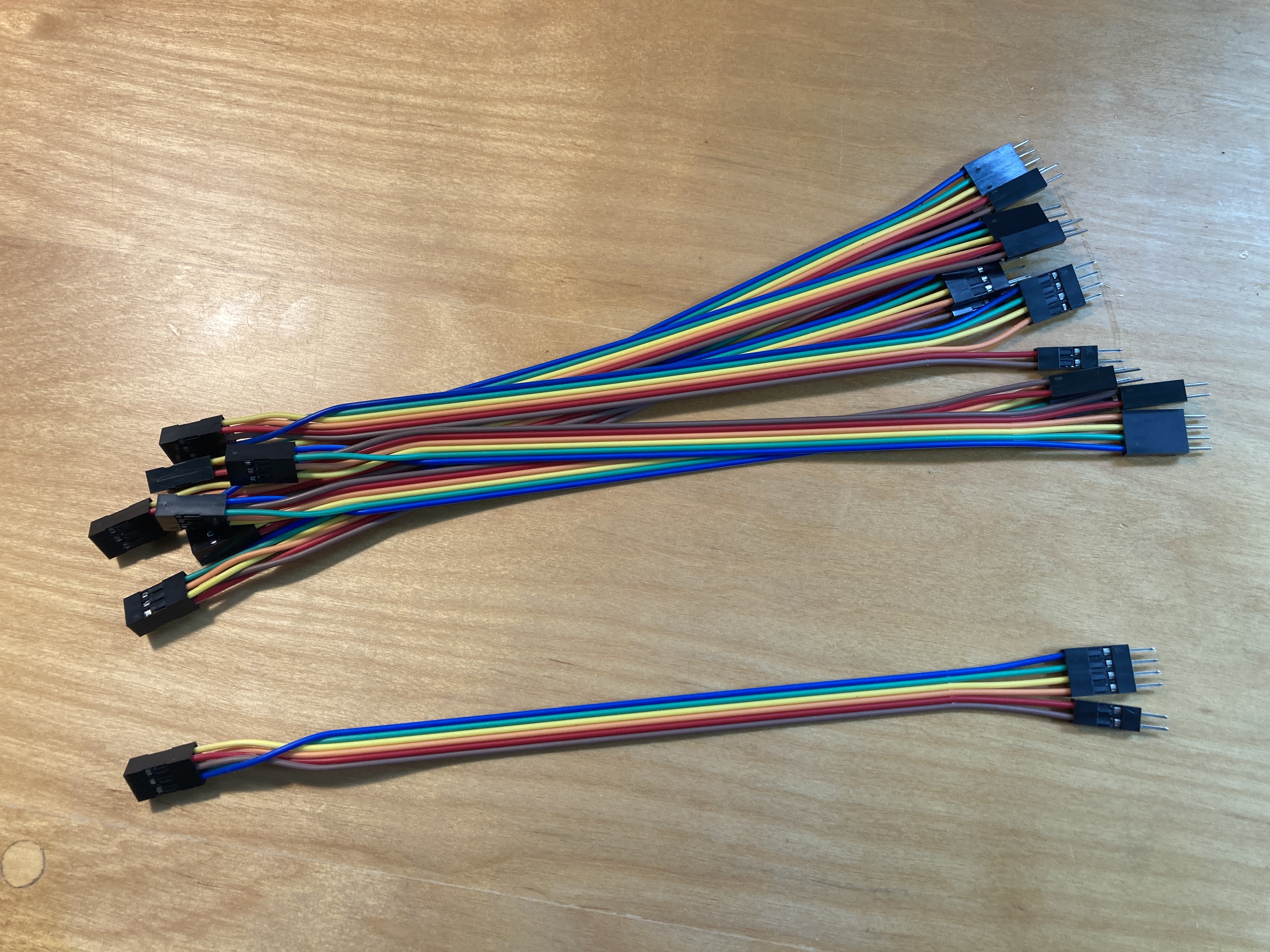
As I mentioned above, this can be programmed via the 2x3 pin header on the pcb. Unfortunately, I chose an incorrect footprint for the 2x3 header when I designed the pcb, so the pins in this header are in an unconventional order for an ICSP. Thus, I’ve provided a custom made programming cable to the folks in the Brightworks community who wanted one of these consoles.
But first, the Uno must be loaded with the “ArduinoISP” script from the Arduino IDE (File > Examples > 11. ArduinoISP > ArduinoISP).
Also, ATTiny Core is required. Follow these directions to install it in your Arduino IDE.
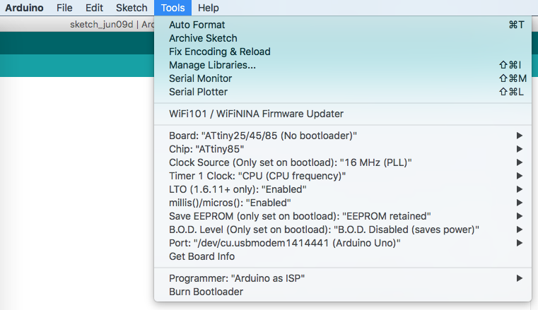
After ATTiny Core is installed, in your Arduino IDE, go to Tools and set the following selections:
- Board: “ATtiny25/45/85 (No bootloader)”
- Chip: “ATtiny85”
- Clock Source (Only set on bootload): “16MHz (PLL)”
- Timer 1 Clock: “CPU (CPU frequency)”
- LTO (1.6.11+ only): “Enabled”
- millis()/micros(): “Enabled”
- Save EEPROM (only set on bootload): “EEPROM retained”
- B.O.D. Level (Only set on bootload): “B.O.D. Disabled (saves power)”
- Port: [whatever port your Uno is on]
- Programmer: “Arduino as ISP”
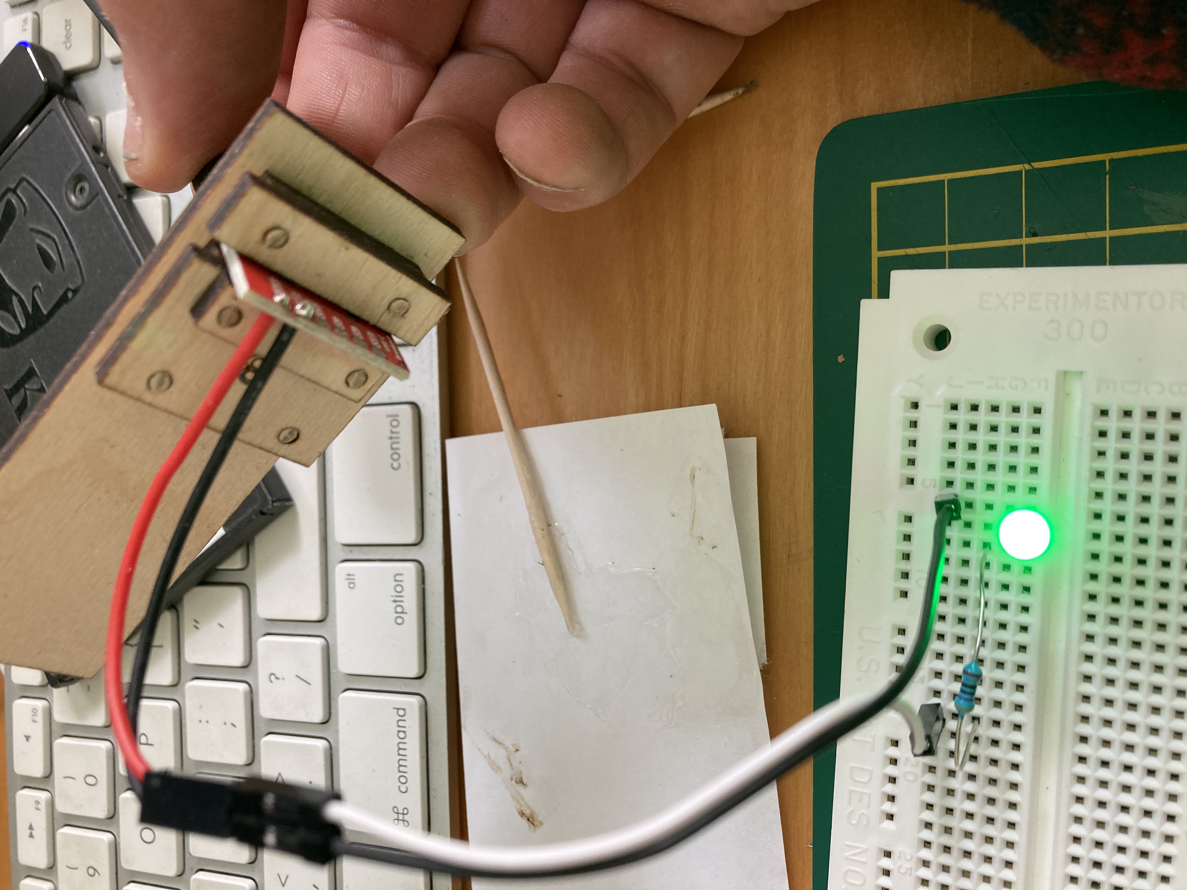
Then connect the cable to an Arduino Uno as follows: red to Vin and brown to GND, and orange, yellow, green, and blue to 10, 11, 12, and 13. On the tiny arcade pcb, make sure the red wire is in the left foreground as you face the display (see photo) when you plug it into the 2x3 header.
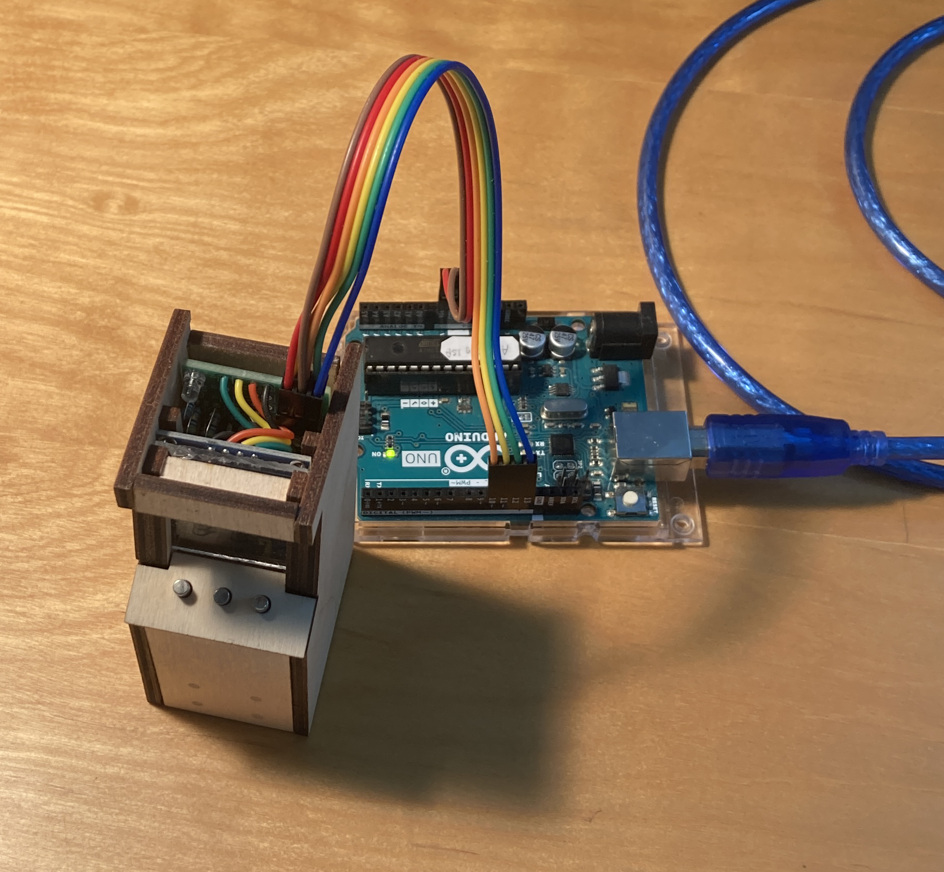
Then Tools > Burn Bootloader. Load the program “reset_tiny_mario_high_score”. Load the program “check_for_0_high_score”; the LED on the tiny arcade pcb should light up if the high score was successfully set to 0 in EEPROM. Finally, load the “tiny_mario_49” program. Disconnect the programming cable, plug in a USB-C cable for power, and start gaming!
How to Change the Difficulty Level
Now that you know how to program the console, here's how to change the difficulty level.
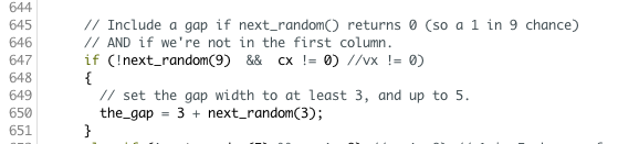
Around line 615 of “tiny_mario_49.ino” is a procedure named get_world(). This procedure generates the world Mario moves through a little bit in advance of him getting there. Down around line 647 is a line that includes “if (!next_random(9)...”. This line sets a 1 in 9 chance of generating a gap that Mario can fall into. Making the number bigger will give fewer gaps, and making it smaller will make more of them.
A few lines below that, at about line 650, there's “the_gap = 3 + next_random(3);”. This sets the width of a gap being generated. It will be at least 3 bricks wide (because of the first 3), and may be up to 1 or 2 bricks wider than that (because of the next_random(3)). Changing these to make wider gaps makes the game harder!
Results
The game isn’t perfect, but it is pretty good and, most importantly, is pretty fun to play. So I think folks who wanted one will be satisfied with them. Plus, they can compete to get the highest score!
Things I Learned
- Glowforge setting for kiss cuts on Avery labels: 500 / 40%.
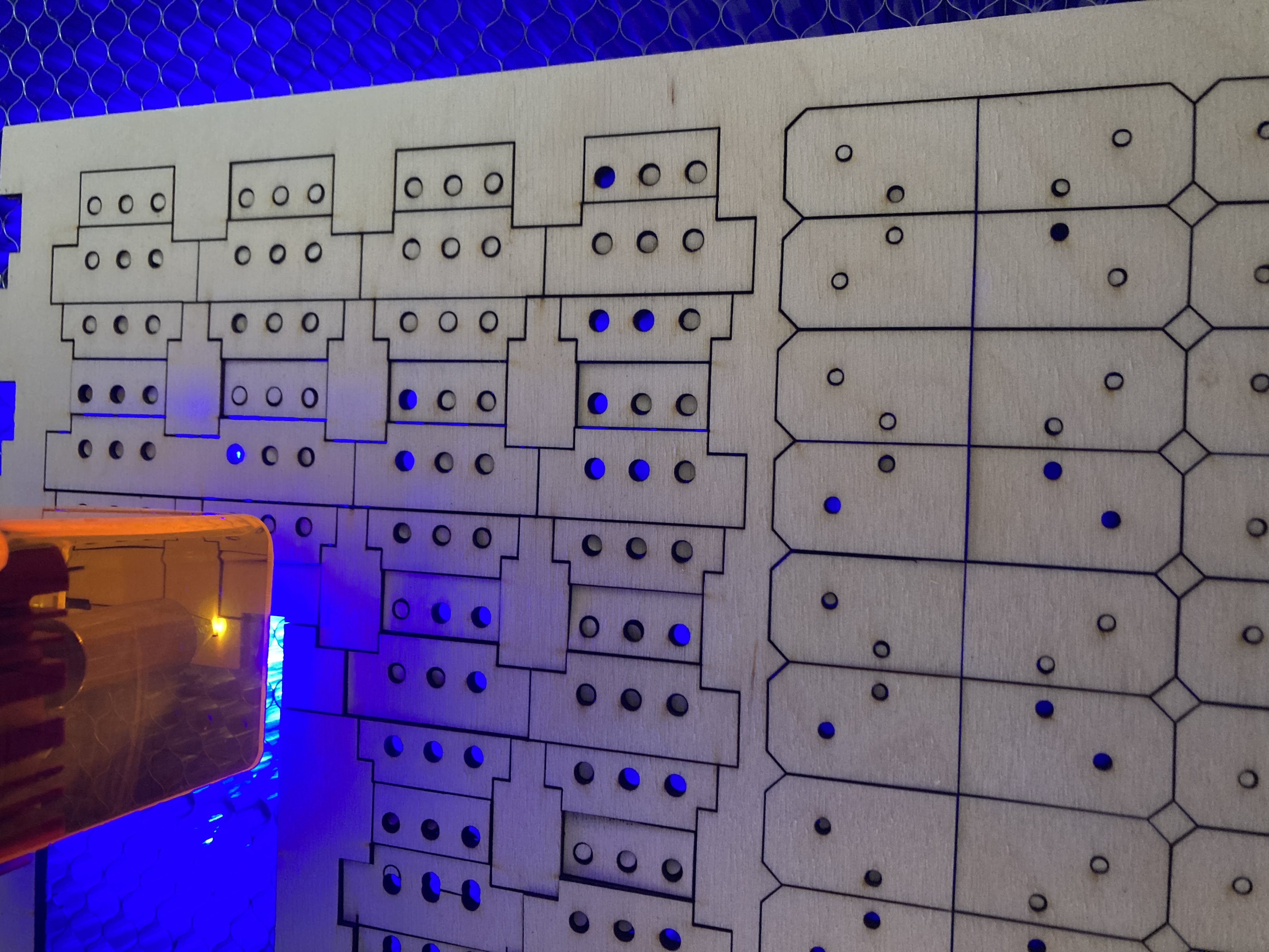
- Use a diode laser with air assist to cut the parts; the Glowforge leaves everything smoke-stained and messy.
- Double-sided adhesive sheets worked miraculously well for attaching the laser-cut guides to the laser-cut side pieces (attach the sheets to the back of the plywood the guides will be cut from before laser cutting them).
- I learned a bit about manipulating registers in the ATTiny85 directly from C.
- The angles around the upper front faceplate (above the display) are awkward for accurately gluing. I kept them though to faithfully recreate the shape of the full-size Game Jam cabinet. If I do this again, I will redesign that part of the cabinet to make it easier to assemble.
Future Directions
If I make more of these consoles, I'll have to have more pcbs made since I used all of the ones that I ordered earlier this year. Since I'll have to do that, I may tighten up placement of components, maybe even try using SMD components (or having JLCPCB do the assembly). For sure I’ll fix the ICSP header so it has the standard ICSP pin arrangement, and add the resistors in the I2C part of the circuit. And I’ll probably add a 0.1 uF decoupling capacitor across Vcc and GND (I haven't experienced any problems in the current units, but it’s cheap and easy to do and might save problems down the road, so why not?)
I may give some thought to programming via the USB-C port instead of the ICSP header, and perhaps will look into expanding EEPROM with an AT25C256 chip (or something similar).
Mods
Within a few hours of getting his tiny game jam console, Atticus already had a useful hardware mod: open the console and switch the orange and yellow leads from the buttons to the pcb. This switches the order of buttons from the default (left button is move left, middle is jump, right is move right) to left button is jump, middle is move left, and right remains unchanged (move right). This is sensible because Mario rarely needs to move left in this game and it makes two-thumb operation easier, with less chance of accidental left movement.
But be careful pulling on the wires: they're small and the crimping won’t withstand being pulled. So use a knife or fingernail to slide the switches’ Dupont connectors off the headers on the pcb, and if you want to remove other ends of the wires from the level limit switches, use needlenose pliers to pull up only the crimped part of the spade.
Thanks Atticus!
Thanks to Supporters
Finally, a big thank you to folks who have supported this project:
- Atticus
- Noah
- Naomi (and Nathaniel)
- Chris (and Isaiah)
- Ariadne
- Ayan
- Jaylen (Mr. Chen)
- Carah Jo
- Ethan
- Rich
Thank you!